Rexroth A10VSO28DFR1/31R‑PPA12N00 Variable Axial Piston Pump
Model clarification and positioning
The correct short code for this open‑circuit, pressure/flow (load‑sensing) controlled 28 cm³ variable pump is A10VSO28DFR1/31R‑PPA12N00. Do not confuse it with A10VO pumps (different family). This unit is widely used in mobile and industrial open‑circuit hydrostatic drives and features load‑sensing pressure limiting and power‑limiting for high efficiency and stability. The control does not replace a system relief valve.
Key specifications
Item | Value |
|---|---|
Displacement (Vg) | 28 cm³/rev |
Nominal pressure (p nom) | 280 bar |
Maximum pressure (p max) | 350 bar |
Max. continuous speed at Vg max | ≈ 3000 rpm |
Max. speed (size‑dependent) | up to ≈ 3600 rpm |
Control | DFR1 pressure/flow (load‑sensing) |
Direction of rotation | R = clockwise (viewed on shaft end) |
Sealing | P = NBR body / FKM shaft seal |
Shaft | P = tapered 1:5, key per DIN 6885 |
Mounting flange | A = ISO 3019‑2, 2‑hole |
Ports | 12 = SAE flange ports, side, opposite, metric screws |
Through drive | N00 = without through drive |
Notes: Ratings and dimensions are per A10VSO size 28 data; always confirm the complete type code and data sheet for your variant.
Code breakdown
A10VSO = swashplate variable pump, open circuit
28 = nominal displacement 28 cm³/rev
DFR1 = pressure/flow (load-sensing) control, hydraulic with pressure limiting
31 = product series
R = rotation clockwise (L = counterclockwise)
P = sealing: NBR body / FKM shaft seal
P = shaft: tapered 1:5, key DIN 6885
A = mounting flange: ISO 3019‑2, 2‑hole
12 = ports: SAE flange, side, opposite, metric screws
N00 = no through drive (other codes available for tandem/auxiliary pumps)
This breakdown aligns with Rexroth’s standard A10VSO ordering rules.
Performance and application guidance
Flow is proportional to drive speed and swashplate angle; DFR1 maintains set pressure while varying displacement to meet demand, reducing heat and improving response.
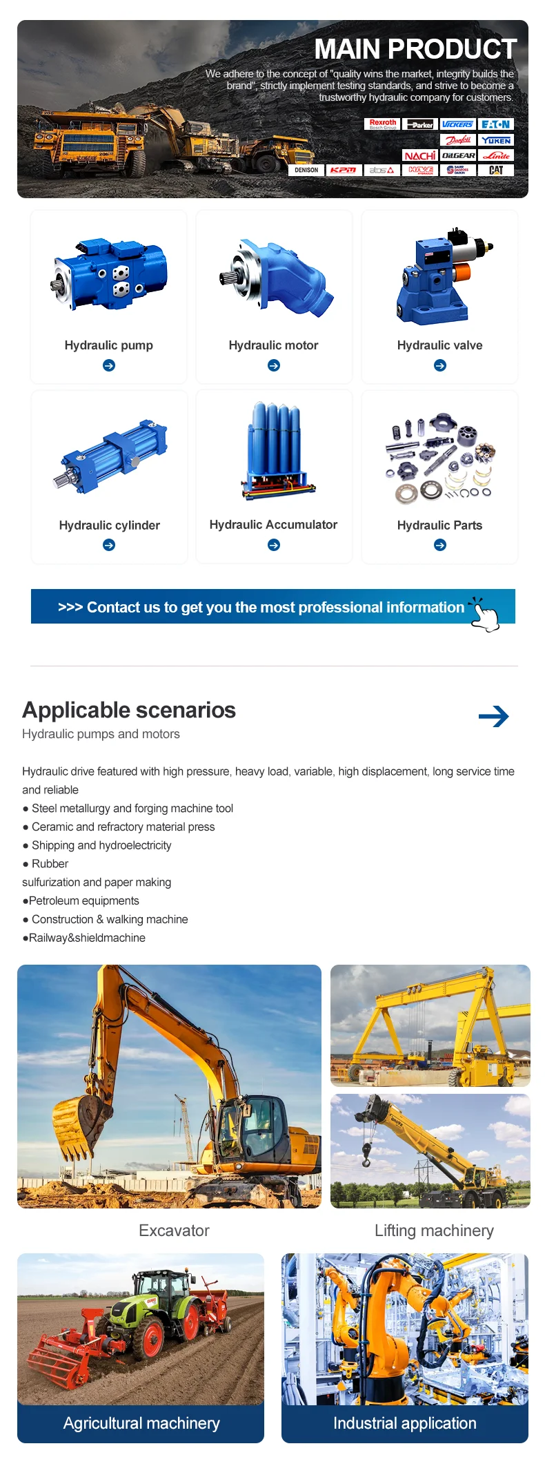
Suited to open‑circuit systems in construction machinery, machine tools, die casting, and general industrial drives; commonly paired with proportional valves for closed‑loop control strategies.
For continuous operation, respect p nom = 280 bar and n max up to ≈ 3000–3600 rpm (size‑ and control‑dependent); ensure adequate suction and system filtration.
Installation and commissioning essentials
During start-up and operation, the unit must remain filled with oil and properly vented; re‑prime after long idle periods.
Maintain minimum suction pressure at port S ≥ 0.8 bar (absolute); avoid cavitation.
Both case drain lines must return below the minimum oil level and remain free of pressure build‑up; the maximum allowable case drain pressure is 2 bar above S (but not exceeding 2 bar absolute).
Oil cleanliness: maintain at least ISO/DIS 4406 20/18/15; if oil temperatures exceed 90°C, cleanliness should be at least 19/17/14.
Recommended operating viscosity: 16–36 mm²/s at working temperature; minimum 10 mm²/s (short time), maximum 1000 mm²/s (short time, cold start).
Safety note: pressure control/limiting functions do not provide overpressure protection—fit a system relief valve. Project planning, assembly, and commissioning should be performed by qualified personnel in accordance with Rexroth instructions.