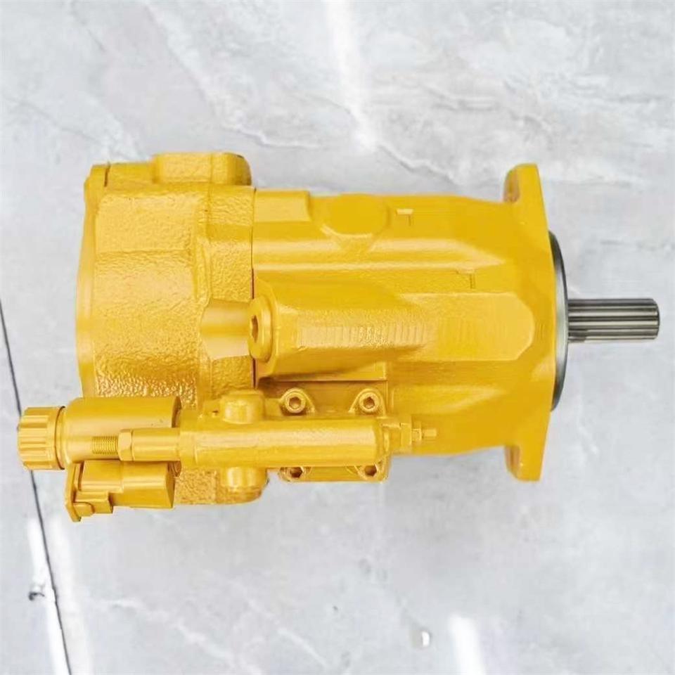
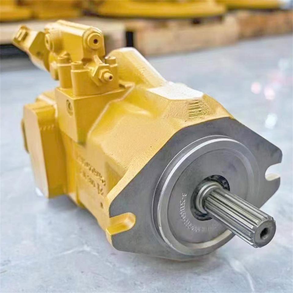

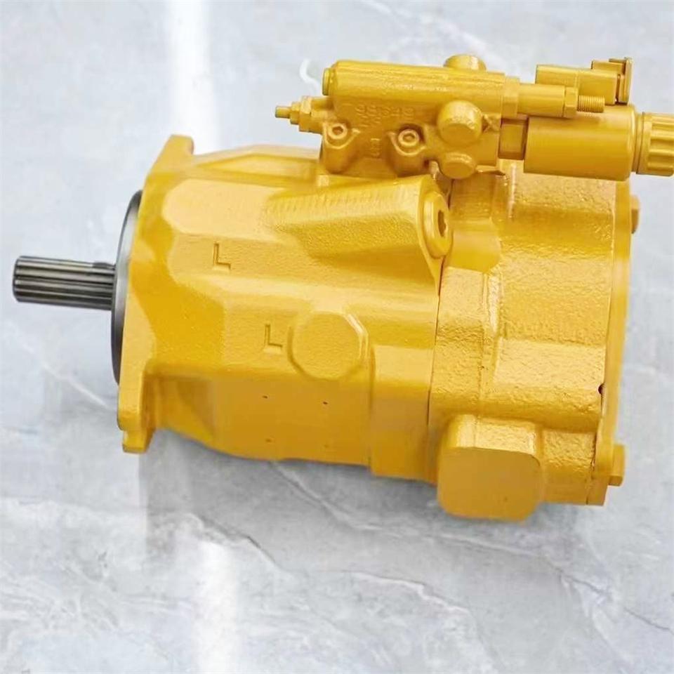
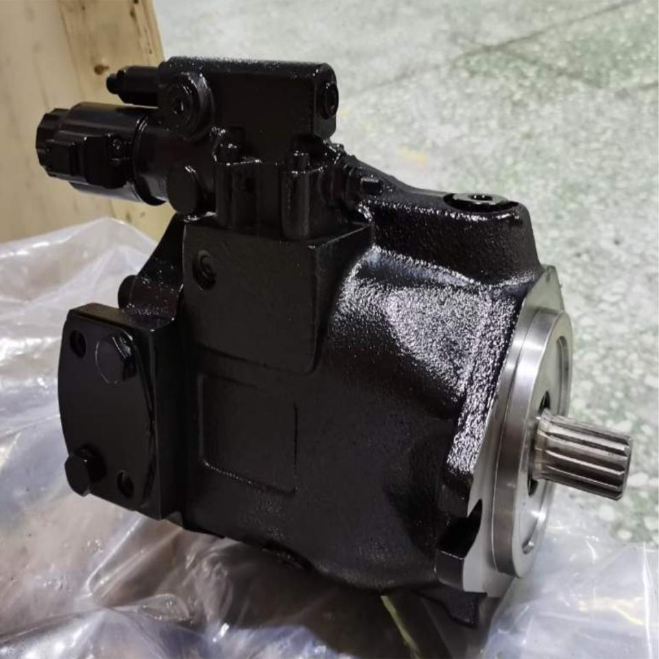
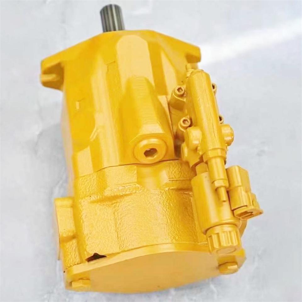
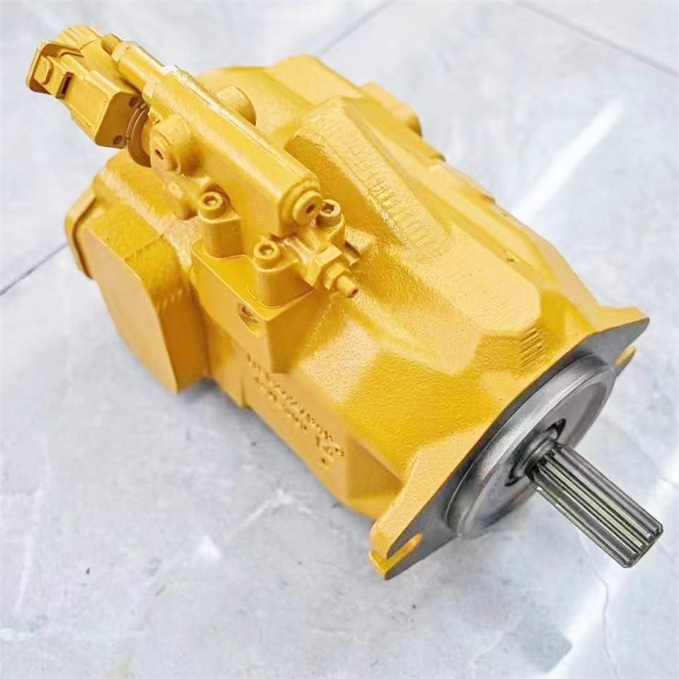


Caterpillar 950K 950M 962K 962M 525D 535D 545D 555D Hydraulic Pump 419‑8920
Overview and Applications
Genuine CAT hydraulic pump assembly 419‑8920is the main implement pump for 950K/950M/962K/962M Wheel Loaders and 525D/535D/545D/555D Wheel Dozers. It is a variable‑displacement, pressure‑compensated piston pump supplying the loader/dozer hydraulic circuits in open‑center, load‑sensing systems. Typical machine serial prefixes include K‑series: LBX, SRF, JRF, LRS; M‑series: LBP, R9P; D‑series: B1K, B2K, B3K, B4K. The pump is commonly referenced with reman p/n 10R-xxxx in CAT’s exchange program (verify the exact suffix by serial prefix). Cross‑fitment listings in aftermarket catalogs also show compatibility with 289‑6370; always confirm by serial prefix and configuration before ordering. Typical pump body ports include T1 (discharge), T2 (load sense), T3 (pilot pressure), and an SOSoil sampling port for condition monitoring.
Key Specifications and Identification
Part numbers: 419-8920(new), 10R-xxxx (reman; exact suffix per machine serial).
Function: Variable-displacement axial-piston pump for open‑center, load‑sensing implement/steering circuits.
System type: Closed‑center load sensing (CLSS).
Typical performance (machine specification, varies with engine speed/control settings): on 434E loader, pump flow approx. 41.0 gpm (156 L/min)and system pressure up to 249 bar (≈3611 psi); use as reference only—actual delivery depends on application and tuning.
Identification: Pump tag and port layout (T1/T2/T3/SOS) are the fastest ways to confirm correct assembly for the target machine.
Part Numbers and Ordering
New CAT: 419‑8920.
Reman CAT: 10R‑xxxx(exchange; exact suffix must match serial prefix/configuration).
Aftermarket listings: 289‑6370 appears as an alternative/new aftermarket p/n in some catalogs; confirm fitment by serial prefix, configuration, and pump tag before purchase.
When ordering, provide: machine model and serial prefix, engine (e.g., C7.1/C9.3), loader valve type (mechanical or pilot), and required options (e.g., seals, shaft/flange).
Typical Fitment Examples
950K — LBX00001‑UP, SRF00001‑UP, JRF00001‑UP, LRS00001‑UP
950M — LBP00001‑UP, R9P00001‑UP
962K— LBX00001-UP, SRF00001-UP, JRF00001-UP, LRS00001-UP
962M — LBP00001‑UP, R9P00001‑UP
525D — B1K00001‑UP
535D — B2K00001‑UP
545D — B3K00001‑UP
555D— B4K00001-UP
These prefixes and others are documented for the 950/962 K/M and 525/535/545/555 D families and are used to ensure correct pump configuration.
Installation and Maintenance Notes
The pump control valve incorporates the torque control and flow compensator adjustments; the T2 load‑sensetap is typically accessible from the cab for diagnostics and tuning.
The hydraulic oil filter is located on the left frame rail; ensure the filter bypassis functional and oil cleanliness meets machine S·O·S targets.
Post‑installation: bleed air, verify LS pressure differential, check for noise/heat, and recheck case drain flow and filter condition after the first few hours of operation.